I
remember the Year June'1990 to May'1994, days of my alma mater, having had to carry a
3kg wooden drawing board with a bag containing all my drawing instruments from
my hostel room to the college in the Manipal Institute of Technology campus –
thrice a week for the first three years. How I cursed those discomforts, my
5’1”physical stature had to face with. No wonder, I pined for something more
comfortable rather than undergo this painstaking task that made me dread that
subject timing periods (not the subject, mind it!) not because the subject was
easy or difficult; on the contrary it was the most professional subject and I
learnt to approach it in the most professional way. That is why they say
engineering drawing is essentially the language of engineers.
Fortunately,
my tryst with the drawing subject did end the way I had always dreamed of it
but in my final year of engineering. A full 3 months contact programme on
AutoCad was held as an extra – curricular programme outside the defined
syllabus for we outgoing students by the Mechanical Engineering Department. A
new CAD/CAM laboratory was initiated in the department in line with the
changing industrial trends at that time wherein AutoCad was taught to us and
demo given on the various CAM operations. Such an opportunity then was rare to
get in any other engineering college as such subjects were still in their
infancy in India at least. The AutoCad – Release 10 ran on then MS - DOS
operating systems and we could get a feel of the AutoCad – Release 11 on the
Window system too at the end of the certificate programme.
So
here I present a post based on a learning that in AutoCad we could draw on
an‘n’ number of invisible transparent sheets whereas in conventional drafting
works we work entirely on one drawing sheet.
Abstract:
In
the realm of drawing, there are a number of methods available for depicting the
details of a given object. The fundamental orthographic projection system
consists of two intersecting planes; horizontal plane and vertical plane which
are at right angles to each other forming four angles or quadrants between them
with only the first and third quadrants being suitable for the projections
while the others are not suitable. In the post below the First angle projection
is considered for illustrating the theme of Layers.
If now the details of the
same object required is in multiple changes be it due to change in customer
feedback, design, manufacturing process parameters, etc. then the same object
needs to be drawn again and again and also retaining the previous made drawings
as reference drawings. This repetitive drawing process would involve lot of
drawing sheets in the conventional draftsman’s job or would involve a lot of
files in AutoCAD. This is where Layers could be used to draw the various changes,
all in one file. By keeping the required layers ON and others OFF a particular
detail of the object is visible and also can be plotted on the drawing sheet in
optimum time.
Introduction:
“Ref.
[1]” quotes that the development of AutoCAD software for IBM PC’s was one of
the first of its kind breakthrough in the application of CAD (Computer Aided
Drawing) for day to day operations as prior to that the traditional CAD systems
ran on the main frame computers with very high costs. As a result, the CAD at
that time was to be a prized possession meant for large corporations who could
afford the cost of main frame computers as well as the large costs that were
associated with CAD software. In 1983, the AutoCAD system was first made
available for the IBM PC computer which appeared in late 1981. The
configuration though had no comparison in terms of RAM, hard disk capacity,
graphic resolution or speed of operation it was a still a major breakthrough since
a large number of users with limited budgets could now afford to use CAD for
their own work. The AutoCAD that was available then had limited capabilities as
was that happened with the scientific calculators whose various functions may
have never been always 100% utilized as long as it was sufficing the works of
those days. However, the designers of AutoCAD have, from the beginning, made it
open - ended with a large number of facilities for customization and extension
making it very popular among a large number of professionals who would be using
it for all types of applications for any time to come.
In
this technical article one such facility was studied in the form of Layer
command which is focused for the work of the engineer/draftsman, to enable him
to depict a variety of details of an object with the minimum available
capability of the AutoCAD software package i.e. the Layer command concept could
be utilized by the engineer/draftsman from the lowest versions to the advanced
versions of AutoCAD.
Layers
Drawings
normally consist of lot of information which is of varying types such as
geometric and alpha-numeric. The geometric information may be further
classified based on the purpose. Similarly the alpha-numeric information also
can be classified into various categories. It becomes difficult to see all this
information in one frame because of the cluttering effect it produces. Also it
is not necessary to have all the information as suggested by [1].
Experimental
section
To deal with this, the layer concept is used
in drawings. A layer is basically one which contains some information which can
be geometric and alpha-numeric. The reason of distributing all the information
present in the drawing into various layers is that at any given time some of the
layers can be deleted from view (OFF) or can be made visible (ON). This helps
in organising the information in a drawing. Thus each layer may be considered
as a transparent sheet with information present. At any stage the unwanted
layers may be pulled out leaving only the requisite information visible as
suggested by [2].
Going by suggestions of
[1, 2] it was experimented whether certain drawing elements i.e. geometric
information alone could be stored in separate layers or not.
Consider the object as
shown below in Fig.1. If a situation demands that the orthographic projection
as well as sectional projection are to be documented or simply displayed on the
computer screen then the given steps could be followed.
Install and start the
AutoCAD software package.
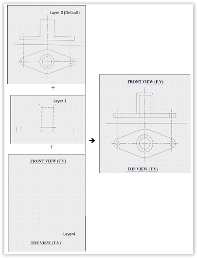
Step1: Draw the entire
orthographic view in the default layer 0. Draw the simple Front View and Top
View depicting the details of the given object.
Step2: To draw the
sectional view certain drawing elements from Layer 0 are transferred to other
Layers.
Step3: The drawing
elements not required in sectional view are changed to layer 1, say.
Step4: The non graphic
elements are also changed over to another Layer 4, say.
Step5: The Layer 0 now
contains the framework which is common to both the orthographic view as well as
sectional view.
Step6: In this common
framework make the drawing elements including the non graphic elements
identified with sectional view.
Step7: Transfer these
drawing elements into a new Layer 2, say.
Step8: Transfer the non
graphic elements into another Layer 3, say.
Step9: Putting now the
Layers 0, 1, 4 ON and other Layers OFF a simple orthographic view was displayed
as shown in Fig.2 and can be plotted using plotter.
Step10: Putting Layers 0,
2, 3 ON and other Layers OFF a sectional view was displayed as shown in Fig.3
which can also be plotted using plotter.
Figures and sketches
 |
|
Fig.1 Object under study
|
 |
|
Fig.2 Orthographic
Projection
|
 |
|
Fig.3 Sectional
Projection
|
Results and discussions
The availability of less
expensive computers and their increasing capability to do various tasks, have
made today’s AutoCAD the basic tool for all engaged in the engineering
profession.
The use of Layer command
could provide the engineer/draftsman the necessary help in the following ways:
·
Computer aided drafting becomes faster and more accurate than
conventional methods. (Refer Step 5 onwards for sectional view in Experimental
Section).
·
The various construction facilities available in AutoCAD, would make the
job of developing the drawing a very easy task for the draftsman (Refer the
simple steps in Experimental Section).
·
In contrast with the traditional drawing methods, under this method it
was possible to manipulate various dimensions and distances of the drawing
elements and storing them in different layers and could be produced as plotted
drawings when needed.
·
Under this method you would never have to repeat the drawing of any
component. Once a component has been made, it could be utilised in all further
works within seconds (Refer Step 5 in Experimental Section).
·
Provides a pleasant and aesthetic presentation if the available further
facilities of Layer command would be utilised such as linetypes, colours, etc.
·
Modification of drawings would be very easy and make the designer’s task
of improving a given product simple enough to take care of any future
requirements.
A point to note is that
the Layer concept of drawing was tested on simple pictorial views as taken from
[3] to be converted into orthographic and sectional views but the sectional
plane could be changed in any orientation/s for a single object to determine
the hidden details in that orientation/s.
Conclusions:
The traditional method of
filing a number of drawing changes can be eliminated by storing the various
changes in the AutoCAD file in as many layers as possible. Whenever
documentation of the drawings is called for then putting On the respective
Layers will enable the plotted drawing to be made available.
This method of drawing
could be easily grasped by engineers/draftsmen who would be well aware of each
and every minute details of the object in hand and also well versed in what
layers would the required drawing changes be contained. As certain objects
would be repeatedly tested there could be changes going into hundreds of
Layers. Hence naming the appropriate Layers ought to be given utmost
importance.
To end I need admit that
passing out at such a changing point in time I did surely miss the opportunity to evolve with many new upcoming
CAD/CAM programmes held not only in my alma mater then (beyond May'1994) but also after that in my professional work experience even till date today. So, the saying 'Make hay while the sun shines' seems apt as one may encounter a wide varieties of learning medias' today but conditions favorable to learn comes only as an opportunity.
Hope this post was educative???
References:
[1]P.Nageshwara Rao
AutoCAD 14 For Engineering Drawing Made Easy. Tata McGraw-Hill Publishing Company
Ltd., First reprint 2000.
[2]Daniel Raker &
Harbert Rice Inside AutoCAD. BPB Publications, New Delhi in arrangement with
New Riders Publishing, First Indian edition,1987.
[3]N.D.Bhatt & V.M
Panchal Elementary Engineering Drawing (Plane and Solid Geometry). Charothar
Publishing House, Anand, India, 47th edition.
No comments:
Post a Comment